
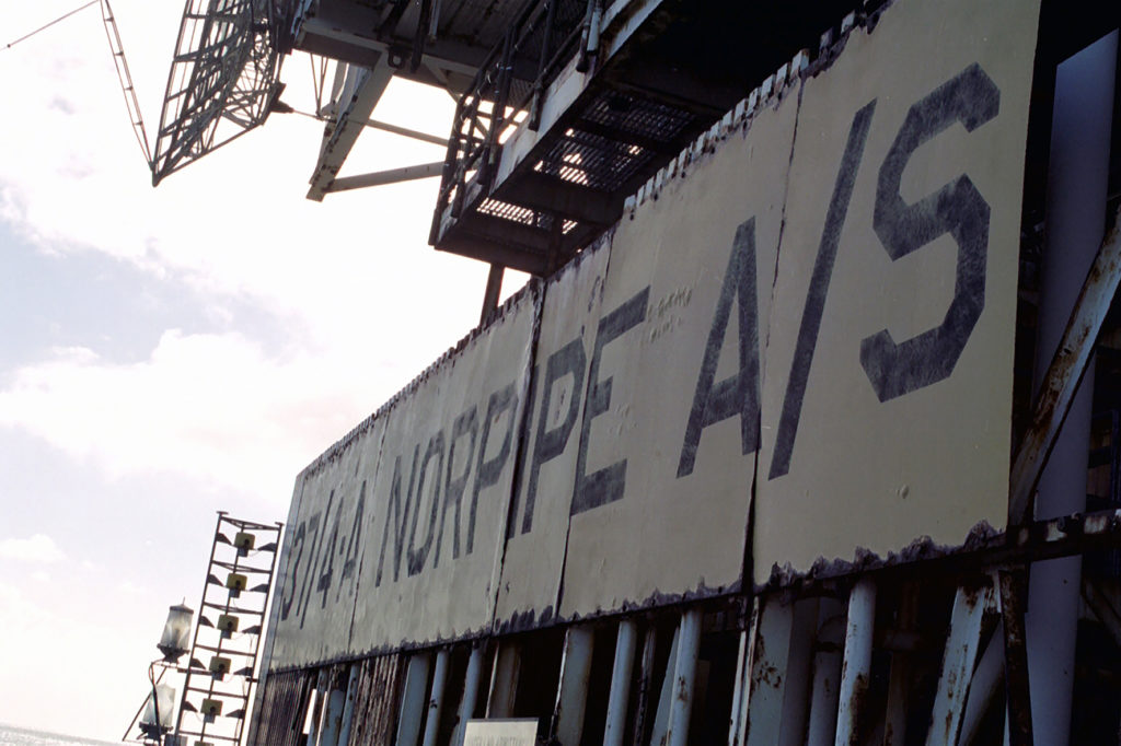
Norpipe 37/4 A

The steel jacket (support structure) and module support frame (MSF) for 37/4 A were fabricated in France by UIE at Cherbourg and St Wandrille respectively.
Installed in 1974, the platform became operational in 1975 but it was 1978 before the quantity of oil in the pipeline reached a level where the two pumping platforms needed to start up.
Oil flowed from Ekofisk 2/4 P in the Ekofisk Complex to 37/4 A and on via the second pumping platform, Norpipe 36/22 A, to the Teesside terminal.
It was decided in November 1981 to cease pumping from 37/4 A, and the section with equipment for this function was disconnected from the rest of the pipeline.
The accommodation module was modernised in 1981, but the turbines were shut down completely in 1983 and the platform ceased to be occupied.
 Norpipe 37/4 A
A pipeline bypass around the platform was installed in 1994. While the 37/4 A topsides were taken to land in 2009, the jacket was removed in 2010.
The platform workforce comprised 10 people, including eight employed by Phillips – the offshore installation manager, a nurse/radio operator, and six pipeline operators. In addition came the steward and a service person from Norske Chalk. Trades covered by the operators included electrician, mechanic, crane operator and telecommunications.
Equipment
Three GE (MS-3002J) two-stage axial turbines (11 800/14 400hp)
Three Bingham one-stage centrifugal pumps
Pigging equipment
Generator room with three Bergen Diesel generator sets, each 640KVA
Two-storey accommodation module with 24 beds – two double cabins and five four-bed cabins
Helideck dimensioned for a Super Puma
Fire pumps and lifeboats
Pipeline to Teesside
 Ekofisk 2/4 P,
Crude oil and gas from Albuskjell, Cod, Edda, Eldfisk, Tor and West Ekofisk were combined on Ekofisk 2/4 T. Together with Ekofisk’s own production from Ekofisk 2/4 FTP as well as crude oil from the Ula and Valhall areas, all the oil was transferred to Ekofisk 2/4 P for onward transport to Teesside.
The oil received in Teesside has a high vapour pressure. Natural gas liquids (NGL) were therefore removed and the crude stabilised for storage. The NGLs were fractionated and sold as ethane, propane, iso-butane and normal butane.
Ekofisk oil was initially loaded into tankers on the field for transport to refineries. The 34-inch pipeline to Teesside in the UK was laid in 1974 and became operational the following year.
 Norpipe 37/4 A,
Running for about 350 kilometres, this installation was given an external protective coating with cathodic protection against corrosion. It was laid in water depths from 75 to 105 metres.
The oil was initially boosted to the required pressure by the pumps on Ekofisk 2/4 P in the Ekofisk Complex before entering the pipeline.
Two pumping stations were installed along the pipeline in the UK North Sea – 37/4 A, about 123 kilometres from the Ekofisk Complex, and Norpipe 36/22 roughly 112 kilometres further on and some 113 kilometres from the receiving terminal at Teesside.


Process equipment
 Norpipe 37/4 A,
As a booster platform, 37/A 4’s process facilities consisted solely of pumps and associated utilities. Three gas-turbine-driven centrifugal pump units, each of 13 075hp, were installed in series.
Each of these comprised a General Electric Frame-3 gas turbine driving a Bingham one-stage centrifugal pump through an English Electric reduction gear.
Fuel came either from a diesel oil tank or from the crude pumped through the pipeline. In the latter case, the oil had to be degassed and thoroughly treated to prevent corrosion.
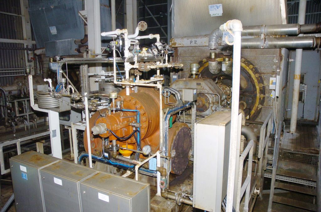
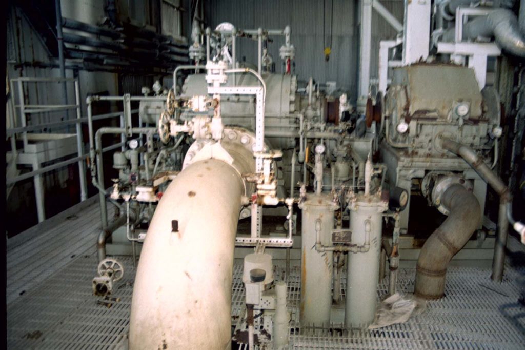 Norpipe 37/4 A, pumpeenhet
Utilities on the platform included telemetry and communication systems, safety and hydraulic systems, power generation, fuel systems and lube oil, and instrument and working air.
Among others were chemical injection, pig launchers and retrievers, salt, jetting and fire water systems, untreated and drinking water, gas blowdown systems, oil recovery, steam generation, and cranes and lifting equipment.
The pipeline was re-laid in 1994 to bypass 37/4 A, which was removed in 2009-2010.