
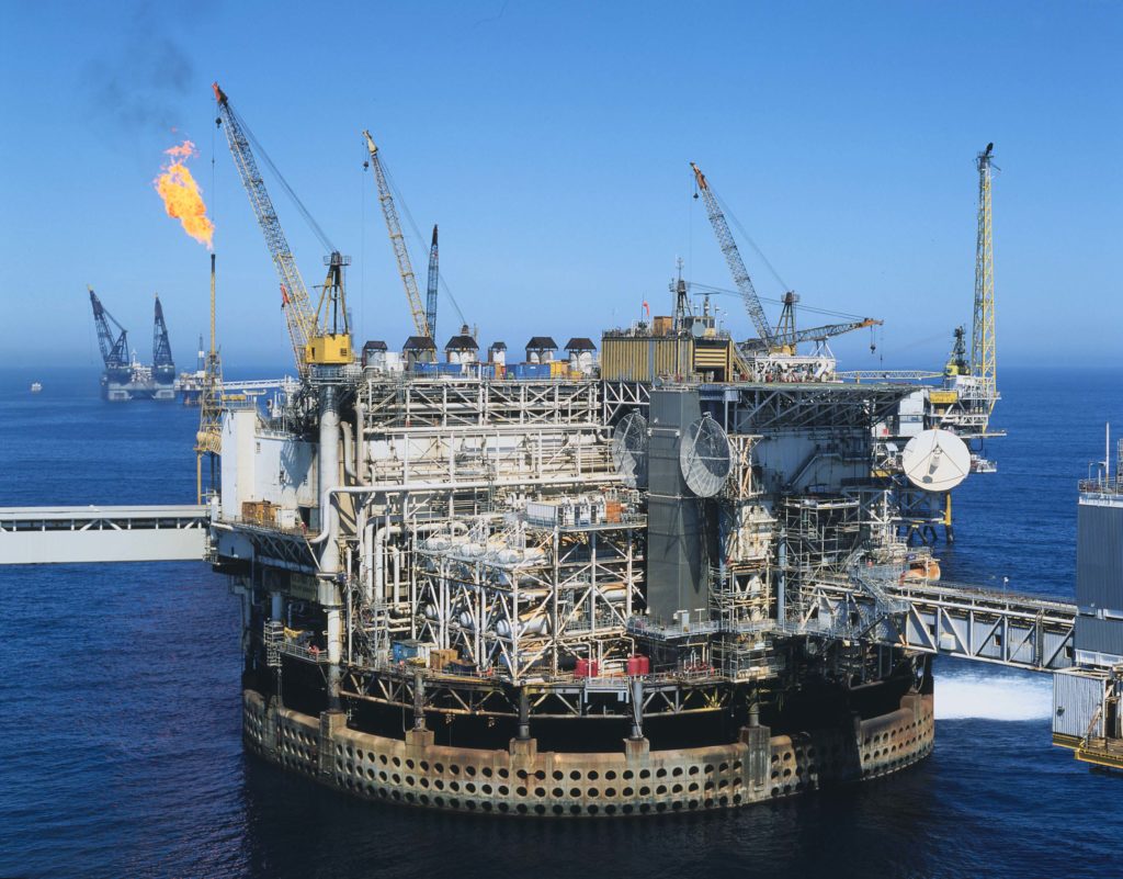
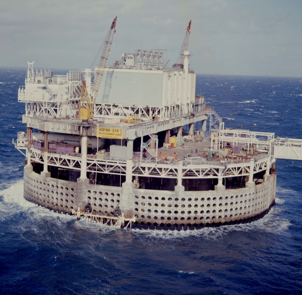
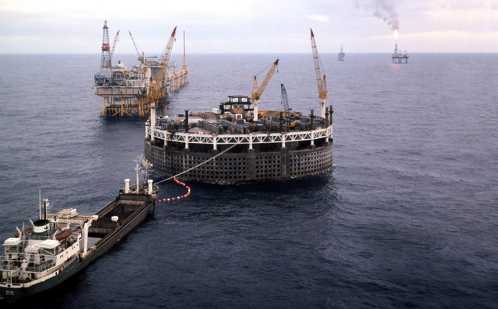
Ekofisk 2/4 T

It was installed on the field in the summer of 1973, and became operational the following year. The pipeline transporting oil and NGL to Teesside in the UK came into operation in the autumn of 1975. The 2/4 T facility was later converted into a substantial processing plant. Because of seabed subsidence on the field, an additional concrete barrier was installed around 2/4 T in 1989. The tank was shut down in 1998 and the systems purged. While the topsides were removed in 2004-07, the concrete structure remained and was fully purged by 2009.
Development of the Greater Ekofisk Area has progressed through several phases:
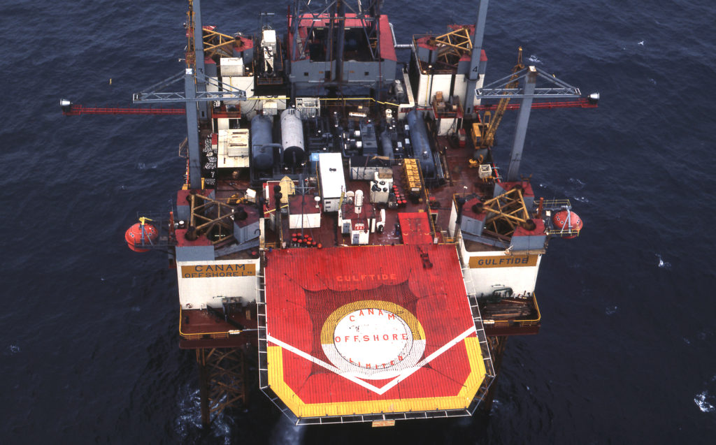
Phase I involved starting production from four subsea wells in 1971. These produced 40-50 000 barrels of oil per day through flowlines to a separation facility installed on the Gulftide jack-up rig.
Gas from the separators not used for power generation or for internal purposes was burnt off in a flare boom installed on the rig. Oil was pumped to two loading buoys for transfer to shuttle tankers. All four subsea wells were later plugged, secured and abandoned.
The second phase covered permanent installations for producing almost 300 000 barrels of oil per cay. This 1974 development included the 2/4 T tank, able to store up to one million barrels of oil, the Ekofisk 2/4 A, Ekofisk 2/4 B and Ekofisk 2/4 C drilling and production platforms, the Ekofisk 2/4 FTP processing facility and accommodation platform Ekofisk 2/4 Q. Gulftide was removed and the loading buoys relocated so they were tied back to 2/4 C.
Starting in 1977, phase III involved completing the development of the Greater Ekofisk Area and the two pipelines with associated pumping stations for transporting
- oil to Teesside in the UK
- gas to Emden in Germany.
 Den store rekorddagen på Ekofisk, historie, forsidebilde, Åpning av oljeterminalen i Teesside
 Phillipsgruppen inngår salgskontrakt for gass, forsidebilde, historie,
New decks were installed on 2/4 T to carry a large processing plant. Equipment there included systems for separating water, oil and gas as well as for dehydration and compression of the separated gas.
Additional discoveries were subsequently tied in – Tor, Cod, West Ekofisk, Albuskjell, Edda and Eldfisk. Production from fields not operated by Phillips – Ula, Gyda, Valhall/Hod and developments served by the Statpipe pipeline – was also sent to the Ekofisk Complex.
 Ekofisk 2/4 T, plattformer
After oil began to be exported by pipeline to Teesside in 1975, 2/4 T lost its original role of storing crude while waiting for tankers to load.
It nevertheless continued to be used for intermediate storage of oil waiting to be piped to the UK. This was intended to separate out the final water residues, which had time to sink to the bottom of the tank if the oil spent long enough there.
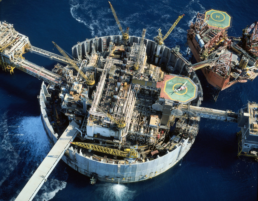
Bridges linked 2/4 T with Ekofisk 2/4 R to the north, Ekofisk 2/4 G in the west and Ekofisk 2/4 P to the south.
Seabed subsidence on the field meant that all the platforms in the Ekofisk Complex except Ekofisk 2/4 S were jacked up by six metres in the summer of 1987.
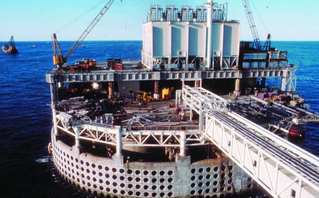
However, this approach could not be used with 2/4 T. Instead, a new concrete barrier was built and installed around the tank in 1989. Its base was constructed in Rotterdam and the actual wall sections in the Ål Fjord near Haugesund in western Norway.
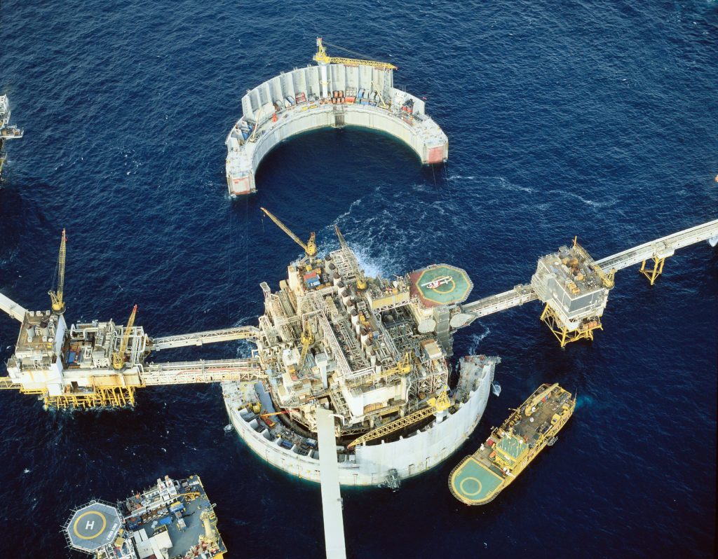 Installing the protective barrier. Photo: Husmo Foto/Norwegian Petroleum Museum
The staged development of the Greater Ekofisk Area provided great flexibility in terms of operational techniques. Normal operation in the field centre utilised both oil and gas pipelines at full capacity and pressure.
Work of preparing 2/4 T for final disposal began soon after its shutdown in 1998. The process facilities were emptied of hydrocarbons by 2000, while clearing the storage tanks took from 2002 to 2005.
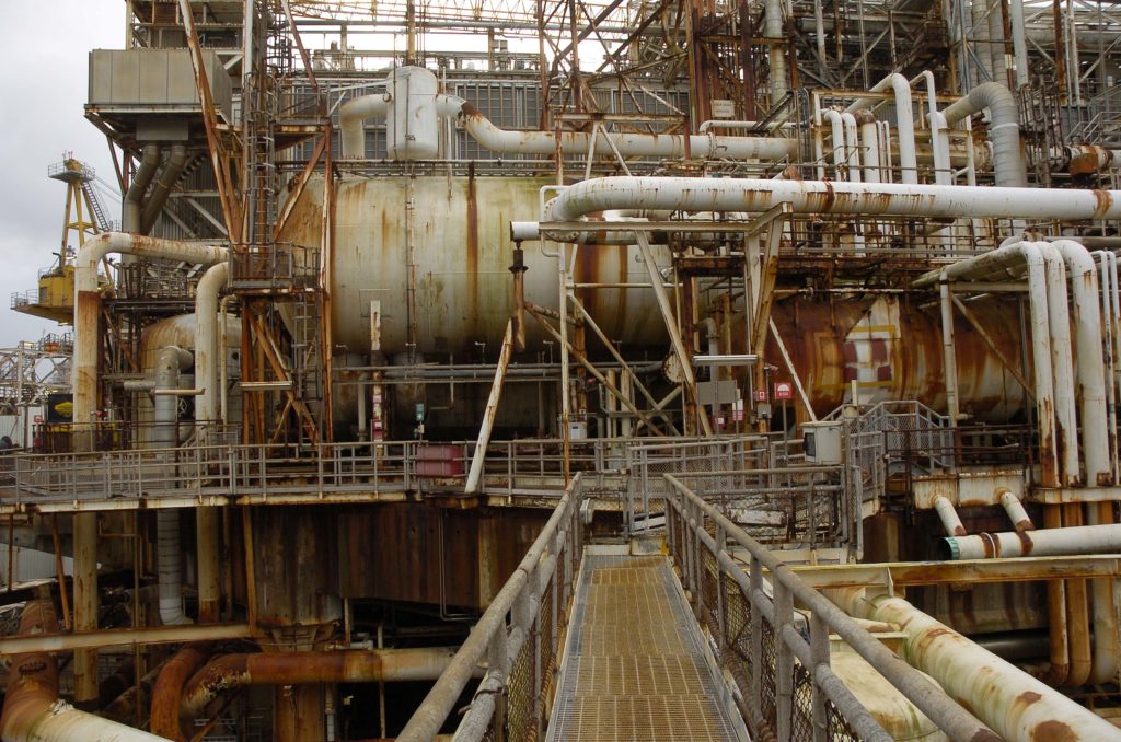
Process facilities
Oil and gas came from the Ekofisk reservoir beneath the platforms at the field centre, and from the Edda, Albuskjell, Eldfisk, Embla, Cod, Tor and West Ekofisk satellites.
Output from other sources – Tommeliten, Ula, Gyda, Valhall/Hod and fields tied into the Statpipe system – also passed through the Ekofisk Complex for onward transport to Teesside and Emden.
 Ekofisk 2/4 T, Tanken
The process facilities on 2/4 T performed the following operations:
- received oil and gas from 2/4 R, Ekofisk 2/4 FTP and Ekofisk 2/4 G
- separated oil, gas and water
- transferred the separated oil to Ekofisk 2/4 P for pumping to Teesside
- stored up to one million barrels of oil*
- dehydrated and stabilised the dew point of the separated gas
- pumped the dry gas to Emden via 2/4 R
- treated polluted water removed in the separation process
- collected process information for all operations on Ekofisk and transferred it to the head office at Tananger outside Stavanger.
The Ekofisk tank was originally built for oil storage. When the pipeline to Teesside became operational, however, it was used for intermediate storage for water to separate out before the oil was piped to land.
Hydrocarbons produced from fields in the Greater Ekofisk Area had to be separated into three components – water, liquid hydrocarbons (mostly crude oil) and natural gas.
The laws of physics state that a liquid will give off gas until a balance is struck between the liquid and the overlying gas. Increasing the pressure or reducing the temperature will convert some of the gas back into liquid.
Crude oil contains the heaviest hydrocarbon, while natural gas comprises simpler and lighter fractions. Between them lie such components as natural gas liquids (NGLs)/condensate, which are liquid under certain pressures and temperatures and gaseous in others.
Varying the pressure in the oil/gas mix will therefore alter the relationship between oil and gas and the composition of these two phases.
Put simply, the 2/4 T process facilities comprised separators for water, oil and gas and a dehydration plant for gas.
Separation
Hydrocarbons were processed on 2/4 T from all the fields connected to the platform. Because of the many stages involved in producing from the remoter installations and bringing this output to the tank, each field had different requirements for oil/gas separation and gas dehydration.
That applied particularly to the pressure of the production flows when they entered the 2/4 T plant. Because this varied from one field to another, the flows had to pass through various facilities in order to even out these differences.
On Ekofisk itself, production from 2/4 A, 2/4 B and 2/4 C was gathered in the 2/4 FTP process plant and separated before oil and gas were transferred to 2/4 T.
Some of the other fields in the Greater Ekofisk Area carried out some degree of initial separation. Combined with gas dehydration, this was done on the Albuskjell, Edda, Eldfisk, Tor, Ula, Gyda and Valhall platforms. The oil and gas were then sent in separate pipelines via 2/4 R or Ekofisk 2/4 G (Valhall) to 2/4 T.
 engelsk, ekofisk 2/4 T,
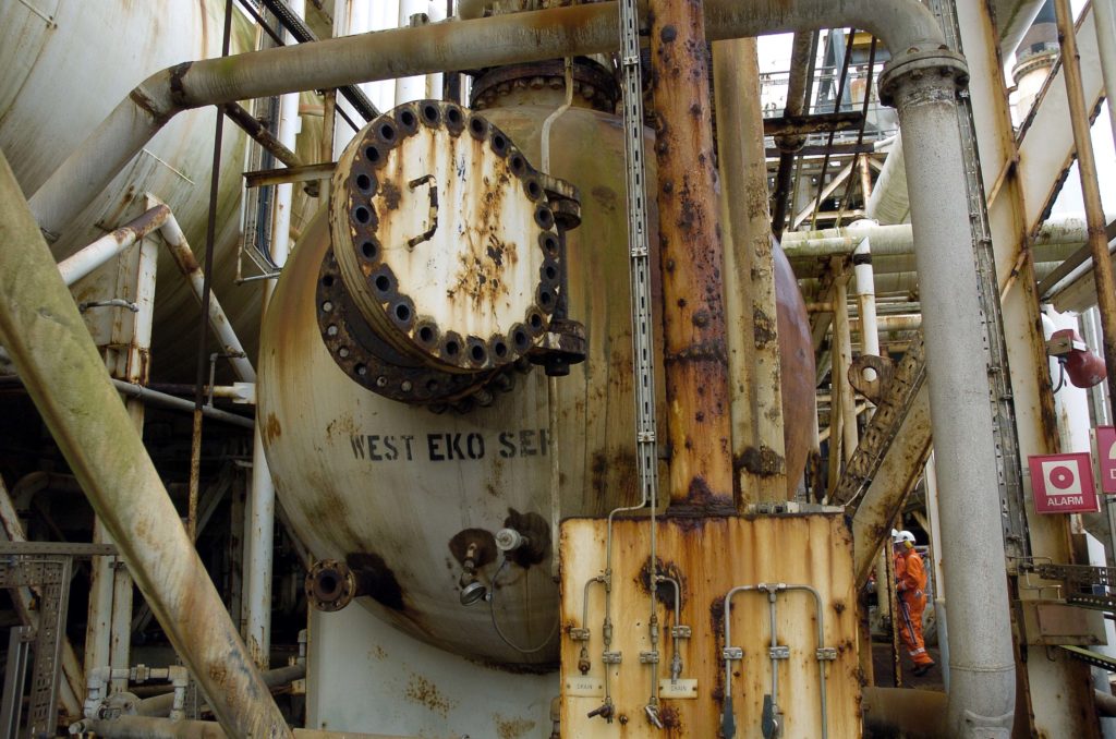
On Cod 2/7 A, both gas and oil were dehydrated after separation and then recombined into a two-phase flow in a single pipeline to 2/4 T via 2/4 R. Gas from Ula went first to Cod for inclusion in its two-phase flow. Gas and oil from West Ekofisk were piped without separation or dehydration in a multiphase flow via 2/4 R to 2/4 T for separation.
The gas from Albuskjell, Gyda and Eldfisk as well as the two-phase flow from Cod were sent first to the dry-gas separator on 2/4 R because pressure in these fields was lower.
Gas from Tor and Edda was led directly to the intermediate-stage separator. From there, it was compressed in the flash gas compressor. The two flows from the 2/4 R dry-gas separator and the flash gas compressor were then combined with gas from West Ekofisk and 2/4 FTP through the booster compressors before entering the dehydration units.
The oil arriving at 2/4 T was also subject to additional processing before being piped to Teesside. Further degassing and vapour-pressure stabilisation took place in the intermediate-stage separator with combined crude and other liquids arriving in the oil gathering pipeline from 2/4 R and from the dry gas separators on 2/4 R and 2/4 T, the West Ekofisk separator, the inlet scrubbers for the stabiliser and booster compressors, and the glycol contactors (dehydration units).
 Ekofisk 2/4 T
The low-stage separators degassed and stabilised the combined crude and NGL from the intermediate-stage separator, the second-stage production separator on 2/4 FTP and liquid from the intermediate- and low-stage scrubbers for the flash gas compressor.
They also recovered and stabilised other small liquid quantities supplied from all the scrubbers for fuel gas, the pig trap on the pipeline and so forth. Pumps for the low-stage separators drove the oil through meters to the pipeline pumps.
Gas dehydration
 Ekofisk 2/4 T, engelsk,
Compressed gas from the intermediate- and low-stage separators was conducted together with the gas from 2/4 FTP, West Ekofisk and the 2/4 R dry-gas separator to the booster compressors. It was then combined with output from the 2/4 T dry-gas separator and sent to the dehydration units.
That was necessary because the gas was saturated with water, which could separate out and cause icing in the dew-point units unless it was removed by putting the gas in close contact with concentrated glycol.
The term “dew point” has two different meanings in this context. While dew-point units remove liquefied natural gas from the gas stream, dehydration units extract water from the gas stream to establish a specific water dew point.
In both cases, the dew point specifies the temperature which a gas stream under a given pressure must be cooled down to in order for condensation to occur.
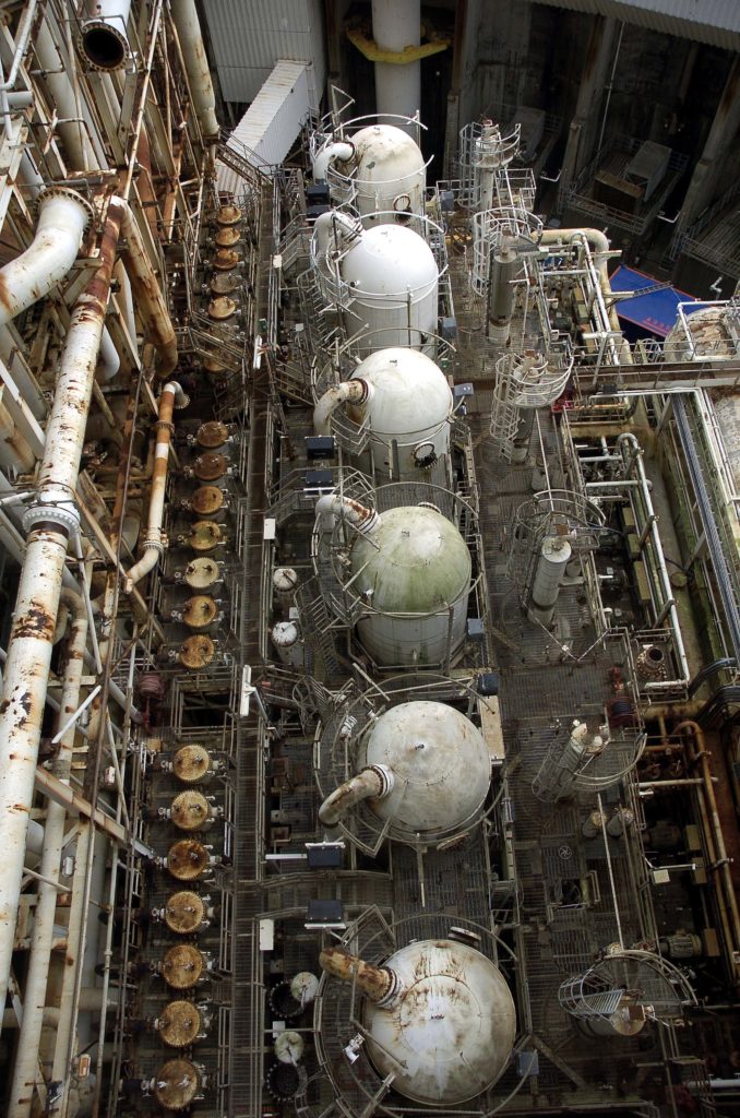
The three dehydration units on 2/4 T each comprised two parallel dehydration trains – six in all. Any of them could be halted independently for maintenance.
 Ekofisk 2/4 T, engelsk,
In addition to water, the glycol solution absorbed a quantity of gas. This was released during the glycol regeneration process and removed together with steam from the glycol boilers. This gas/steam stream was then flash cooled with cold water, compressed by venting compressors and conducted to scrubbers for separating water and gas. The latter was sent to the scrubbers for the low-stage flash gas compressor, while condensate was drained to the oil recovery system.
Each dehydration unit originally had its own compression system for venting gas, but these three systems were later converted to serve all the units.
Dew-point units
These were intended to separate out NGLs – ethane, propane and butane – for mixing with the crude being sent to Teesside. The units comprised three parallel trains, each with two gas-to-gas heat exchangers connected in series, a gas cooler, and a separator and stabiliser for dew-point liquid. The trains had a common chiller system for propane.
 The gas was cooled to a temperature between -18°C and -16°C in order to condense and separate out NGLs. These were mixed with oil from the low-stage separator and sent to the Teesside pipeline. The residual gas from the dew-point stabilisers was used as fuel on the platform.
Gas compression
Stabilised process gas from the gas-to-gas heat exchangers in the dew-point units flowed to meters for sale, fuel and injection. Gas not used for fuel or sent for sale through the pipeline was metered on 2/4 T and piped to compressors on 2/4 C for injection into the Ekofisk reservoir.


The four Dresser Clark gas pipeline compressors were two-stage centrifugal units with five first-stage and four second-stage impellers in a single housing. They were driven by General Electric Frame 5B dual-shaft gas turbines developing 27 300hp.
Gas flowed from each compressor to discharge coolers. To achieve greater operational flexibility, a 16-inch outlet manifold was installed along with an eight-inch recirculation manifold which connected the discharge and recirculation lines from the compressors via manual blocking valves. The gas discharge coolers were six metres tall and cooled by seawater. During normal operator, the gas temperature was reduced to 38°C.
Gas from the coolers was conducted to 2/4 R, where it flowed through two pressure regulation valves and then to the Emden pipeline.
Injection gas was piped from the 2/4 T process to 2/4 C. How much gas was injected by the latter platform’s injection compressors depended on the amount left over after the daily contractual quantity for the gas pipeline to Emden had been met.
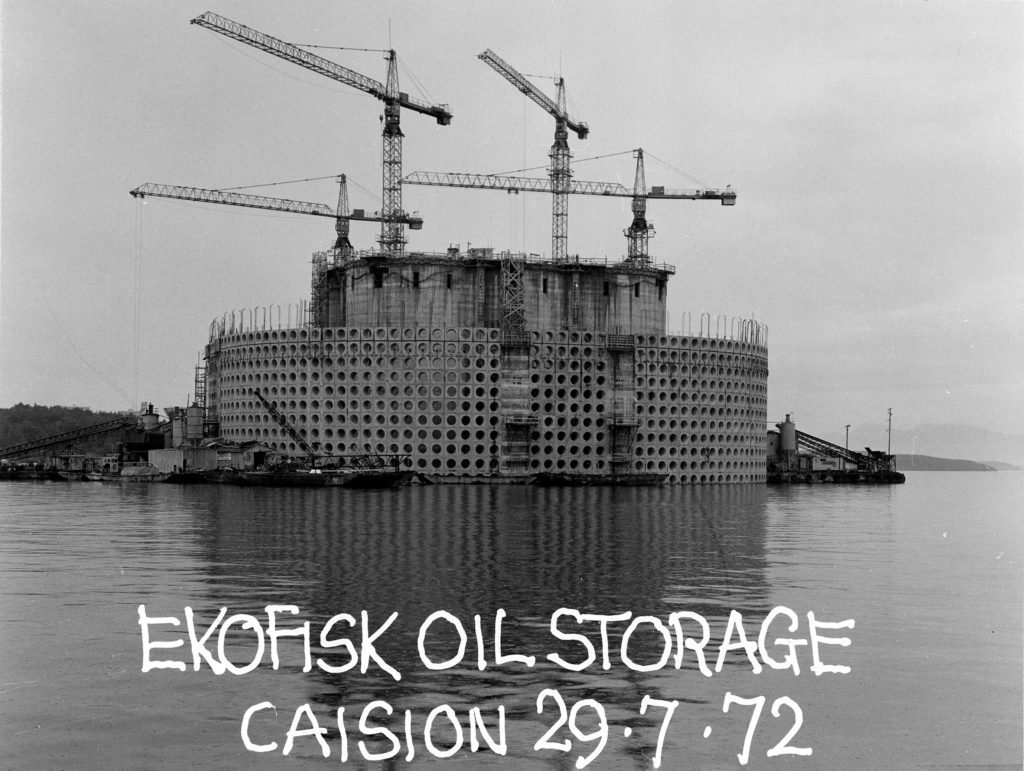
Constructing the tank
The Phillips group entered into a contract on 14 May 1971 with the French company C G Doris for building a concrete storage tank to stand on the Ekofisk field.
This marked the end of an intense decision process which had been under way for several months. A number of questions were raised about the pioneer project – most fundamentally whether the structure would float so that it could be towed offshore from the construction site.
However, all doubt had been swept aside within Phillips and the Phillips group. A good reason for this was the tight timetable which had been set – the tank had to be on the field by the summer of 1972 if the overall development schedule was to be maintained.
That also contributed to the decision to start construction work even though the Norwegian government had yet to give its final formal consent.
Construction site
Even before the contract with Phillips had been signed, Doris got in touch with Norwegian construction company Ing F Selmer to get a non-binding estimate for doing the concrete work on such a tank.
Selmer did a quick calculation and put in a bid. Doris then came back in April-May 1971 with a request for a binding tender – the project was going to be realised.


The Norwegian company had long experience of concrete structures from building hydropower dams, grain silos and bridge supports. It was regarded as the leading specialist on slipforming in country – perhaps even the world.
Selmer had recently completed a big hydropower project in Australia and felt it would not be sensible to tie up all its resources in projects with a tight schedule. Help would be needed.
It turned to Høyer-Ellefsen, another of Norway’s top three construction contractors in this sector at the time, and the two companies joined forces to take on the job.
The first problem which had to be solved – and quickly – was the choice of construction site. This had to satisfy a number of requirements, with a large area suitable for conversion to a dry dock among the most important.
In addition came an infrastructure capable of handling such a large and intensive project with its tight timetable, and sufficiently deep water nearby where slipforming could take place. A water depth of more than 60 metres was also needed for the towout to the open sea.
 oljen forandret stavanger-regionen, engelsk, Ekofisk 2/4 T,
The site noted by Selmer plant manager Knut Tovshus and production manager Gunnar Vindvik was Dirdal, a small rural community at the inner end of the Høgs Fjord in Gjesdal local authority in Rogaland county.
While awaiting for the results of site surveys, an agreement was reached with the landowners. But this was done without involving the local authority, and a row broke out when Gjesdal council learnt about the plans late on 17 May 1971 – Norway’s Constitution Day.
Issues of principle relating to Norwegian local democracy were raised. Local daily Stavanger Aftenblad raised this question in a leader on 19 May, and the affair led to questions in the Storting (parliament).
Gjesdal council indicated that it would have to conduct an extensive planning process before a decision could be taken. In the meantime, Selmer began to hunt for alternatives.
Jåttåvågen bay on the Gands Fjord off Stavanger was chosen, and new site surveys launched. Unlike Gjesdal, the city welcomed the plans with open arms and the planning process was fast-tracked.
Stavanger had learnt that things were supposed to happen fast in the oil industry – and usually did. The city had already demonstrated its ability to meet the requirements set by this “American tempo”.
While discussions about Dirdal versus Jåttåvågen continued, the results of the site survey in Gjesdal revealed that it was not suitable after all. Excavation would need to go down about 40 metres before a dry dock could be secured against water intrusion.
That left the Stavanger site, and even Stavanger Aftenblad applauded this outcome in a leader on 2 June. Vindvik said later that he was happy Dirdal had not been chosen – it would have completely overwhelmed the local infrastructure. Roads, water supply and so forth could not have coped, with the construction work forced to move.
Selmer signed a contract with the City of Stavanger on 4 June. The council stipulated that the dry dock was to be turned into a marina for 550 boats when construction finished.
This deal marked the start of a industry adventure in Jåttåvågen and adjacent Hinnavågen, as a long series of Condeep concrete platforms came to be built there up to the mid-1990s.
Construction start
Stavanger council formally approved the contract with Selmer on 14 June 1971. Work on levelling the dry-dock site had then already begun. Installation of the 300 metres of sheet piling to keep the water out started a week later, followed swiftly by dredging and readying the 110 by 110 metre excavation.
Activity in Jåttåvågen continued throughout the summer, while local companies in the Stavanger area were awarded sub-contracts for the project.
With Doris as the main contractor, French companies Europe-Etudes and UIE had major deliveries. However, Selmer and Høyer-Ellefsen were the biggest sub-contractors with responsibility for construction and concrete work.
Stavanger Spennbetong and O C Østraadt in Sandnes delivered prefabricated components, including about 8 000 sections for the breakwater, Singel & Grussenteret was contracted to supply 120 000 cubic metres of sand, and Norsk Hammerverk provided the 5 000 tonnes of reinforcement steel required.
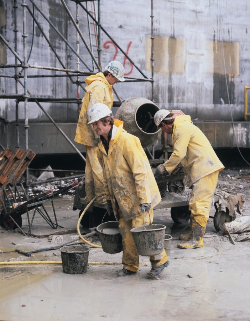
In addition came a mass of minor deliveries. Moreover, the tank project arrived at a time of low activity for the construction sector in the Stavanger area. At peak, the job would employ almost 800 people.
Work proceeded virtually night and day in order to be finished by mid-August, when the actual construction process was to begin. That gave Doris one year to meet the completion date of 1 August 1972.
Construction start delayed
Official approval of the drawings for the tank had still not been received when construction was due to start in the first half of August 1971. This responsibility had been outsourced by the Ministry of Industry to classification society Det Norske Veritas (DNV).
The first problems arose just a day after work had begun. DNV was unable to accept the calculations submitted by Doris for the base slab on the grounds that the strength calculations were inadequate.
It called for new data. That initially resulted in a decision to incorporate ribbed concrete on the underside of the base, rather than the flat surface originally envisaged. This meant the dry dock had to be deepened by a further metre before casting could begin.
While that was being done, DNV came up with new objections to the base slab on the grounds that reinforcement and thickness were inadequate. Construction of the formwork had begun when this intervention halted the whole project on 23 August.
These difficulties naturally arose because no construction experience existed from similar structures. This was the first time concrete was being used in an offshore oil content.
Norwegian standards were not formulated for such conditions, and fresh questions came up as DNV received documentation from Doris.
One problem which quickly emerged was the French company’s unfamiliar with such close official inspection. DNV had therefore been virtually cold-shouldered for a period. By the time it got to see the documentation for the sub-structures, it was far too late and the work had either begun or was on the start line.
This clash with the Norwegian way of working naturally led to delays. Fortunately, action was eventually taken and the climate of collaboration improved substantially.
It was not until 30 September that all the disagreements had been cleared up and the work could resume. Before then, extensive tests had been made with the structure, including at the Norwegian Institute of Technology (NTH) in Trondheim. The result was that the quantity of reinforcement steel was increased and the concrete base made thicker.
Construction method
Originally, the base section was due to be ready for towout from the Jåttåvågen dry dock around Christmas 1971. However, the delays and the additional work they involved meant that this stage was not reached until 24 February 1972.
Slipforming was to take place off Hillevåg further to the north, where the water depth was satisfactory for the technique chosen. The Ekofisk tank was submerged as the work proceeded, so that its height above the sea surface remained virtually constant.
That contrasts with the approach taken to the concrete gravity base structures (GBSs) for the later Condeep platforms, which are built upwards until they top out and submersion only takes place when mating with the topsides.
It was decided the evening before the towout from the dry dock to hold a naming ceremony. Ann Doney, wife of C E “Chuck” Doney, the Phillips representative at Jåttåvågen, was given the honour of being the lady sponsor. So Ekofisk I was named in the finest champagne.
It floats
Plenty of sceptics were convinced that Ekofisk I would be unable to float. How was that possible with a concrete colossus of 45 000 tonnes, they asked? Archimedes’ principle was highlighted in newspaper articles in the run-up to the event, and many critical spyglasses were directed at the tank on the day.
And the tank floated – admittedly with a clearance of only 30 centimetres because of the additional base components. At high tide, however, the operation exceeded all expectations.
Once in place off Hillevåg, the tank was moored to two hydraulic anchoring devices on land while a pair of newly developed mud anchors were extended out into the fjord.
Stavanger Aftenblad published its third leader on the structure under the headline “Ekofisk I”. It wrote that the event was “an oil adventure in our own swimming pool”, and concluded by expressing the wish (parodying the traditional naming ritual) “May good fortune follow you on the bottom of the sea”.
Slipforming
 støping, ekofisktank, 1971 ekofisk 2/4 T
Preparations for the slipforming operation began as soon as the tank was moored. This technique was utilised by Selmer on the nine storage cells in the centre of the installation. The structure which connects these cells with the breakwater wall was also slipformed, while the rings making up the breakwater were prefabricated. These became something of a problem during the work, and the holes had to be temporarily covered during the initial phase to improve buoyancy.
One restriction on progress was the DNV decision that concrete could not be exposed to the sea until it had reached a certain age. That caused some delays because the tank was submerged as work progressed. The result was that the slipforming advanced at about three centimetres per hour – 60 centimetres a day. Work went on around the clock, with 750 people divided into three shifts active at peak.
Things went well until the Easter of 1972, while DNV continued to test the design in Norway’s only ship model tank at the NTH. It was subjected there to the hundred-year wave to measure the loads that would put on the structure in the sea.
Further approval problems
Work on the tank progressed normally during the spring and summer of 1972, and it topped out on 21 June. But a constant tug-of-war was taking place between DNV and Doris – and between the industry ministry and Phillips as the construction client.
While the problems which had arisen when building began had been cleared up, the unusual condition that work started before the drawings were approved continued to dog the project.
Disagreement over strength calculations and stability was so great by the end of March that the ministry told Phillips it ought to halt the work. A hectic series of meetings continued throughout the spring, and independent expertise from the University of Calgary in Canada was brought in.
With the exception of a strike and a few days when strong winds halted work, however, construction continued without a pause. The approval process had little effect on day-to-day work, and the problems were solved along the way with the goal of completion by October 1972.
Outfitting
As concrete construction approached completion, a mass of other jobs were in full swing. A great deal of equipment was to be installed on board in order to provide the capacity to receive 350 000 barrels of crude oil per day – and to pump out 720 000.
Furthermore, treatment facilities were installed to ensure that the cleanliness of the water discharged to the sea was on the safe side of the Norwegian government’s requirements.
This was complex work, and much more extensive than originally expected. Vindvik observed: “I’m not sure we would have taken on this assignment if we’d foreseen all the work it involved. Naturally, however, when we see the consequences, we’re glad it was done.”
Tourist attraction
The bold commitment involved in building the Ekofisk tank made it a target for oil personnel from the whole world during the construction period. Those responsible for the concrete work reported in August 1972 that more than 3 000 people had paid a visit.
These industry specialists wanted to get a closer look at the colossus, and possibly apply its construction principles in their own development projects.
A great many other people were also interested in the structure, but were not allowed on board. The tank became part of the urban scene in Stavanger. Spyglasses and visiting pleasure boats became part of everyday life for the workforce.
Plans change – extensions
Compared with the original plans laid in 1970, the Ekofisk development became steadily more complex during 1972. Six new fields had been discovered – Edda and Albuskjell in 1972 alone, when the scope of Eldfisk was also established. At that point, nobody knew where this would all end. Plenty of potential structures which might yield discoveries remained to be drilled within the licence area.
 Ekofisk 2/4 T, tanken,
Oil and gas processing requirements increased sharply. The process plant on Ekofisk 2/4 FTP had a daily capacity of 350 000 barrels, but this was expected to be sufficient only for production from the main Ekofisk field. More capacity was therefore required to handle the six satellite fields discovered so far – as well as possible additional finds. At the same time, it was definitively clarified that the Phillips group intended to lay two pipelines from Ekofisk to land – one for oil and the other for gas.
The technical solutions involved called for a central starting point. That would allow new fields to be tied in without significant production interruptions – unlike tie-ins to the actual pipeline on the seabed – and offered better overall economics.
Given the concentration of platforms which took shape, with 2/4 C, 2/4 FTP, 2/4 Q and 2/4 T, this was a sensible and logical standpoint. Moreover, the tank top provided an available area of 7 100 square metres virtually free of charge.
A structure originally planned as a storage container thereby became instead the place where all oil and gas from the satellite fields would be gathered and sent ashore.
Schedule overruns
The increased scale of the Ekofisk development meant that all schedules overran, and the original plan to start production from the fixed platforms in early 1972 proved impossible to fulfil.
 Phillipsgruppen søker om prøveproduksjonsløyve, historie, engelsk, forsidebilde,
With the start date constantly being postponed, the government extended the test production licence for Gulftide. That meant in turn that the tank no longer needed to be on the field in the summer/autumn of 1972.
Delays with completing the structure between 1 August and October also meant that Phillips was sceptical about undertaking a towout at a time when it could run into the first autumn/winter storms.
In the late summer of 1972, the Phillips group decided to install a deck over the whole tank and another above that covering 65 per cent of the area. This could have been done out on the field, but would have cost more and increased the risk. Doing part of the work in sheltered inshore waters was safer.
Work on casting the supporting pillars for the lower 20-metre deck began in late September and installation was completed during the winter. The upper deck was to be installed on the field.
Once the 20-metre structure had been completed, it was equipped with facilities which allowed workers to stay there and work on completion – both en route to Ekofisk and after the tank was in position. A helideck was part of this outfitting, since no links with other platforms would be in place initially.
Towout preparations
Preparations for the tow occupied the spring of 1973. The route to be taken had been decided as early as May 1971 by representatives from Doris and Selmer. This was naturally an important element in the choice of construction site.
The tank would draw about 60 metres during the tow, and the most difficult and critical part of the operation was the initial section from Hillevåg to the Høgs Fjord north of Stavanger.
Another important and critical point was the crossing of the Norwegian Trench, the deepwater valley which runs just off the coast of western Norway. However, installation on the field was indisputably the most hazardous job. This had to be done carefully so that no damage was caused to tank, while also ensuring that it would be a resistant as possible to wind and weather.
Discussions had started even before the construction work began, resulting as noted above in the installation of concrete ribbing under the base slab. Site investigations conducted on the field by the Norwegian Geotechnical Institute showed that the seabed comprised a 23-metre layer of sand over firmer clay. Computer simulations had shown that the tank would eventually work its way into the seabed until it was so well embedded that weather conditions would have little impact.
The towout date was set as 8 June 1973. Everything was made ready, and six big tugs providing a combined 45 000hp were in place. A warning to shipping in the area was advertised in the papers. Weather forecasts for the tow period were good – and in the secure hands of a meteorologist Doris had brought from France.
A little over 10.00 on 7 June, the industry ministry gave the green light. Then DNV detonated a bombshell. Less than 12 hours before the tow was due to start, it announced that the documentation of the seabed measurements from the tank site was deficient.
The society was not satisfied with or convinced by the surveys Doris had conducted, and unsure whether the seabed was as flat as the contractor and Phillips had concluded. As a result, the ministry called for new seabed measurements and the tow was postponed.
By 12 June, the Simson tug was in place on Ekofisk to conduct a new survey with the aid of an echosounder. But the weather conditions were not ideal, and doubts again arose over the quality of the measurements.
But analyses began at DNV, where people worked around the clock. The question was whether the results were the same as those obtained by Doris. DNV was worried about big local irregularities on the seabed which could cause crack to form in the tank.
Following the new measurements, it was decided to inject concrete beneath the structure after it was positioned, and thereby create a kind of foundation. This was possible because a tube had been incorporated in the tank, originally to pass measuring devices through.
A green light was thereby given again – this time on 19 June by the Norwegian Petroleum Directorate. But then new problems arose. Some of the mooring chains had already been cut in anticipation of the tow starting on 8 June, but a couple remained in place.
The new start date was set at just past midnight on 20 June. People in the Stavanger area had made their way to the fjordside in the fine summer night to witness the event. But they were disappointed – and had sacrificed a night’s sleep to no avail. The work of severing the mooring chains with flame cutters took longer than planned, and a new delay occurred.
Off at last
At 02.15 on 21 June, the six tugs could finally apply their 45 000hp to the 215 000-tonne tank. Two were positioned in the forefront, two astern and one on each side. A marine operation ranked as one of the biggest in the world until then got under way.
Stavanger Aftenblad devoted its fourth leader to the tank on the same day under the headline “A local world event”, and observed that “the monument to a new technological era is today journeying through our district”.
The tow followed the route which later became the regular passage for the Condeep GBSs from Norwegian Contractors in Hinnavågen. On leaving Hillevåg, it passed Usken into the Høgs Fjord and continued due north between the islands of Talgje and Fogn, then Fogn and Finnøy, around Krabbeskjær and out into the wide Bokna Fjord.
This operation exceeded all expectations, and none of the many contingency plans which had been prepared were required. The tank reached its destination on Ekofisk during 1 July.


Positioning
The structure drew 66 metres during the tow and was to stand in a depth of 70 metres. Water was pumped into the tanks while manoeuvring the colossus into place. A final check of the exact position was made before the tank settled on the seabed.
 Ekofisk-tanken på plass på feltet, forsidebilde, historie
In its original plan, Phillips intended to install 2/4 T on the same straight line as the southern flare stack, 2/4 FTP, 2/4 Q and 2/4 C. However, the uncertainties aroused over the status of the seabed led to a shift a little further to the west – creating the characteristic kink in the Ekofisk Complex.
However, bottom conditions proved better than feared, and the plan to inject concrete underneath the tank could be dropped. In its place, a “skirt” was installed around the structure by driving steel sheets into the seabed to prevent currents from undermining the foundations and creating irregularities.
To secure the tank even further, it was ballasted down with water and sand – the latter incidentally sourced from the original construction site at Dirdal. Almost 48 000 tonnes were shipped from there to the field.
Further work
 Ekofisk-tankens første olje, forsidebilde, historie,
After most of the work of positioning and securing 2/4 T had been completed in the late summer of 1973, Doris began work on installing the 30-metre deck. Prefabricated components were shipped out and assembled on the field.
Completion of the tank in line with the expanded plan for its utilisation went on for a long time and formed part of the field’s third development phase. It was finally finished in December 1974.
This installation primarily served as a nerve centre and production hub for Ekofisk. The need for a buffer store in bad weather disappeared when the pipelines became operational. As back-up in case the transport system was damaged, however, it has provided additional security for production stability on the field.
Consequences
Construction of 2/4 T was a milestone in the Ekofisk development – and a major step forward in Norway’s petroleum history. It is difficult today to imagine oil operations on the Norwegian continental shelf without the concrete platforms.
When the decision to build the tank came to be taken, however, no experience was available to build on. Those responsible took knowledge and techniques from other contexts and combined them to create a new product – which they believed in.
There were plenty of sceptics. The whole construction process was an exercise in boldness. A concrete tank had collapsed during launching in France, and that event cast a shadow over the whole project. The structure was carefully monitored as a result.
That also helps to explain the many interventions by DNV as the official inspection agency. Strength and stability calculations for a concrete tank able to withstand the forces imposed in one of the world’s toughest sea areas were not to taken lightly. Fears about oil leaks with consequent pollution overshadowed most decisions during the petroleum sector’s early years in Norway.
For Selmer and Høyer-Ellefsen, construction of the Ekofisk tank marked the start of a new industrial activity. Experience from this project formed the basis for the platform concepts which later became a reality. And they were realised because the Ekofisk tank demonstrated that concrete was an appropriate material for offshore platforms.
That recognition is not weakened by the fact that the French breakwater concept was abandoned in favour of slimming down the structure as much as possible in the vulnerable splash zone. It merely shows that the companies were able to apply the knowledge and experience they had gained.
In the very year 2/4 T was towed out from Stavanger, the partners in Norway’s Condeep group won contracts to build three new platforms resting on a concrete GBS. These have been followed by many more, with the designs continuously improved and amended. But the Ekofisk tank was the first.
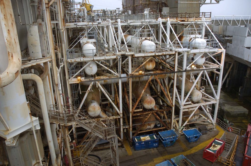
New process plant
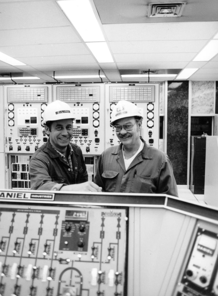 kontrollrom, 1973, arbeidsliv, prosesstekniker,
The 30-metre deck installed offshore by Doris covered 65 per cent of the tank surface, and its prefabricated components were all in place by the spring of 1974.
At the same tine, a total of 72 modules for the actual process facilities were under construction at fabricators around Europe and the USA. The first equipment package was lifted onto the tank in the early autumn of 1974, and was followed by a continuous stream of new units until May 1976.
Hook-up work could begin soon as the first modules were in position, and this job went on until May 1977. It was largely carried out by Brown & Root’s Eumech subsidiary, which relied largely on Spanish and Italian labour. So it was perhaps not so surprising that the six-storey block of containers where they were quartered acquired the exotic nickname of “Chinatown”.
Completion of the process plant on 2/4 T was complicated by the failure to finish the NGL plant at Teesside as planned. This meant the processing facilities had to be converted so the NGLs produced together with the dry gas and crude oil could be injected back into the reservoir by dedicated pumps on 2/4 C. That continued until March/April 1979, when the NGLs could be received at Teesside.
The facilities on 2/4 T almost doubled processing capacity for oil and gas at the Ekofisk Complex. This also required a new safety valve – a second flare stack, which was installed north of 2/4 T.
Source: Kvendseth, Stig, Giant discovery, 1988.