
Ekofisk 2/4 H

Installed in 1977, 2/4 H became operational in 1978 and functioned as the main accommodation facility for the Ekofisk Complex until the new Ekofisk 2/4 L accommodation platform was put in place in 2014. Shut down on 1 September 2014, 2/4 H is due for removal by 2022.
The platform acted as a specialised service facility for accommodation and administrative functions. Providing 212 beds in double cabins, it was linked to Ekofisk 2/4 C by a bridge.
All the facilities required by its residents were provided on 2/4 H, including its own power station and watermaker as well as full catering provision.
In addition came a cinema, gym, games and reading rooms, chapel, coffee lounges, hospital and equipment for technical education. Other provision included storage capacity for a number of technical functions and services for helicopter traffic.
The top management for the whole Ekofisk field was also located there, with offices for the offshore manager and a number of shared services.
Supported on a four-leg steel jacket which alone weighed 3 300 tonnes, the 2/4 H topsides included cellar and main decks which each covered 1 400 square metres.
Above that came a main module made up of four accommodation sections – three of five stories and one of six. In addition came the helideck with hangar. The cellar deck was originally 21 metres above the sea surface.
The actual jacket, all the accommodation modules and the original helideck with hangar were fabricated by Aker Verdal A/S north of Trondheim. A new helideck built by OIS in Kristiansand was installed in 1991. The module support frame and the bridge to 2/4 C were French-built by France Enterprises.
Sky lobby and reception
 Arbeidsliv, logistikk, trafikk, resepsjonist
The primary job of 2/4 H was to provide accommodation for offshore personnel.
Personnel normally arrived at 2/4 H by helicopter, which landed on the seventh-storey helideck. Above this level was a control centre for sea and air traffic. A helicopter hangar and freight reception were also located on the seventh storey.
Arriving and departing passengers passed through a “sky lobby” on the sixth storey. Access to this area was through two doors which functioned as an airlock to maintain a comfortable temperature in the living accommodation.
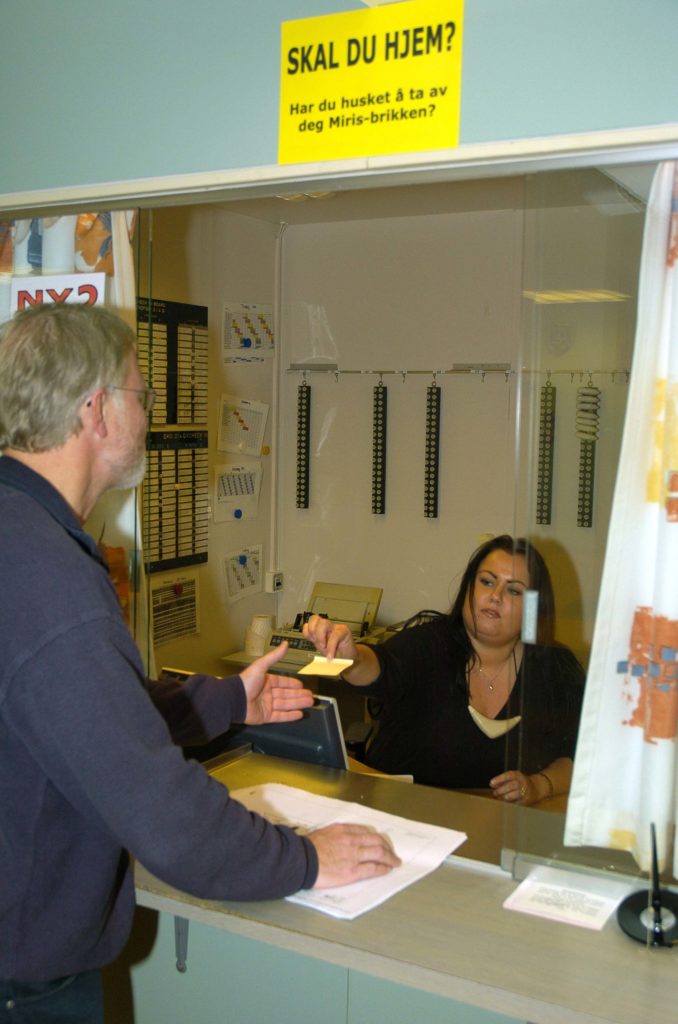
The lobby contained a reception desk, toilets and access to lifts and staircase. A chapel was located in the north-east corner of the sixth storey.
Everyone arriving on 2/4 H was registered. This system was originally entirely manual, but an automated manpower tracking system (MTS) was introduced in 1984. That made it possible to determine the location of each employee at all times.
A new solution, the Miros remote identification system (Miris), was adopted in 1994 and linked to the MTS via satellite. The central Ekofisk Complex is divided into four zones with the aid of antenna portals installed at key points on a number of platforms.
Anyone passing through these portals is registered. That allows Miris to provide an immediate overview of who is in each zone in the event of an alarm, and to clarify quickly if somebody might be missing.
Everyone who arrived on Ekofisk 2/4 H was issued with a Miris chip card which had to be worn around the neck at all times.
 Ekofisk 2/4 H
Cabins and hospital
 Ekofisk 2/4 H,
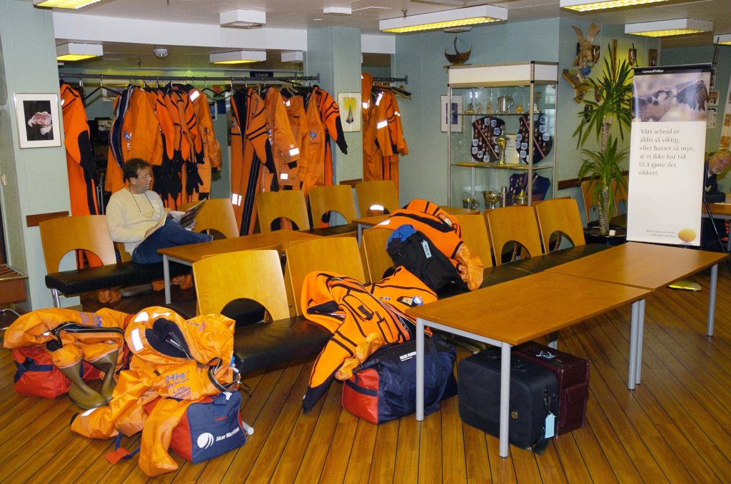
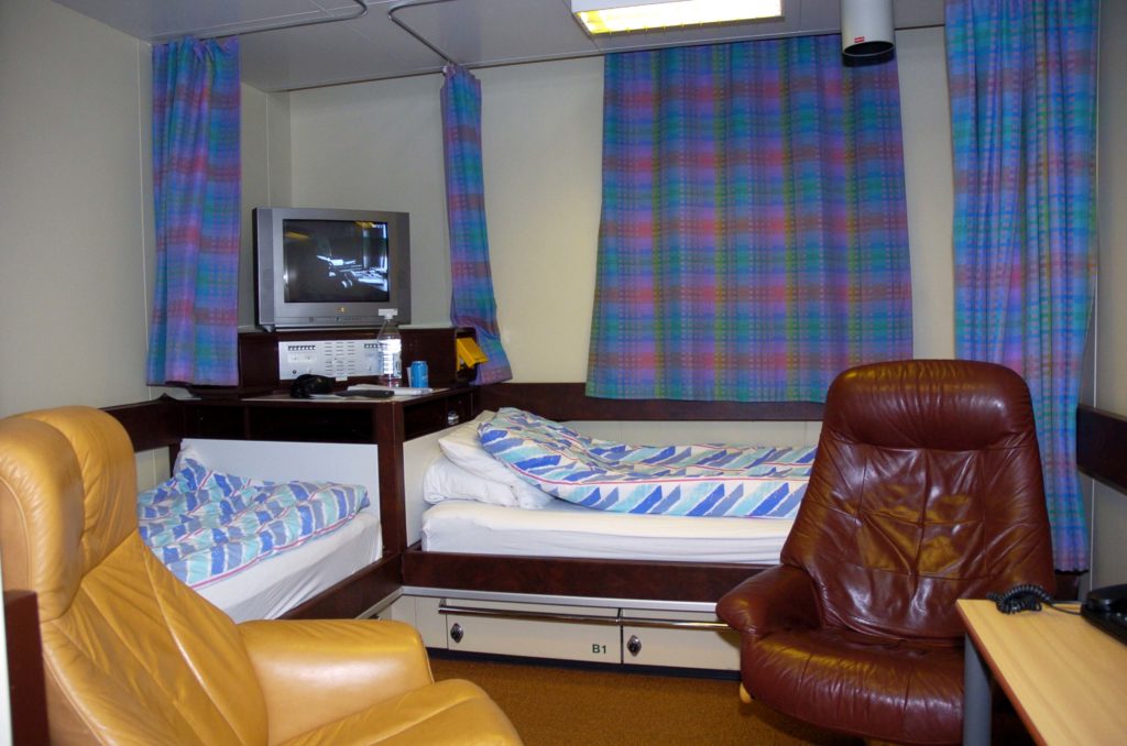
The topmost cabins were on the fifth storey, where 22 double units were provided along the northern and southern sides. Each cabin contained two sofa beds separated by a corner cabinet with TV, radio and reading lamps.
It also had a desk with chairs, six lockable cupboards, some shelves, lockable drawers, wardrobe for survival suits and WC/shower.
The fifth storey also contained stairs, access to the lifts, offices for the administration, shop and gym with exercise equipment, changing room, WC/showers and a sauna.
The floor plan for the fourth storey was similar to the one for storey above, apart from certain areas in the central section. It also contained 22 double cabins, while a room with an electrical switchboard and air conditioning was located centrally.
 Ekofisk 2/4 H,
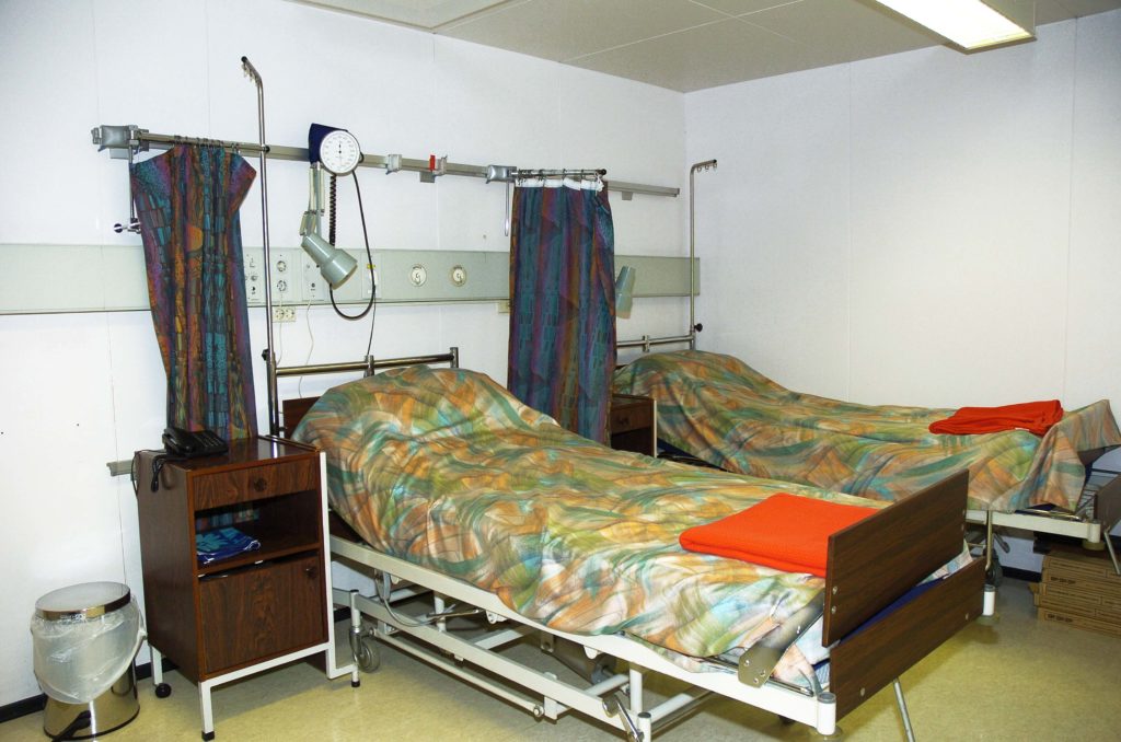
Here were also found a large conference room and a medical clinic (hospital). The latter comprised a waiting room, a treatment room with adjacent WC, an isolation ward with two beds and offices for the senior nurse and the search and rescue (SAR) nurse.
Kitchen, cafeteria and cinema
The floor plan for the third storey differed significantly from the fourth and fifth stories.
It contained 18 double cabins, an 88-seat cinema (plus a 27-seat balcony accessed from the fourth storey), non-smoking lounge as well as reading, computer and pool rooms.
The second storey provided 22 double cabins, while the galley with storage facilities, the 112-seat dining room, the smoking lounge and conference rooms occupied the centre section.


Cellar deck
The first storey contained 22 double cabins, changing room and laundry, and offered direct access to lifeboats 1, 2, 3 and 4.
The deck below the first floor had 28 addition cabins, changing room, offices and access to lifeboats 5, 6 and 7.
Facilities on the cellar deck included two cold rooms, two walk-in freezers, three dry storerooms for catering personnel, the battery room, tanks for diesel oil, air compressors with tanks and the watermaker. An exit led to lifeboat 8.


Helideck
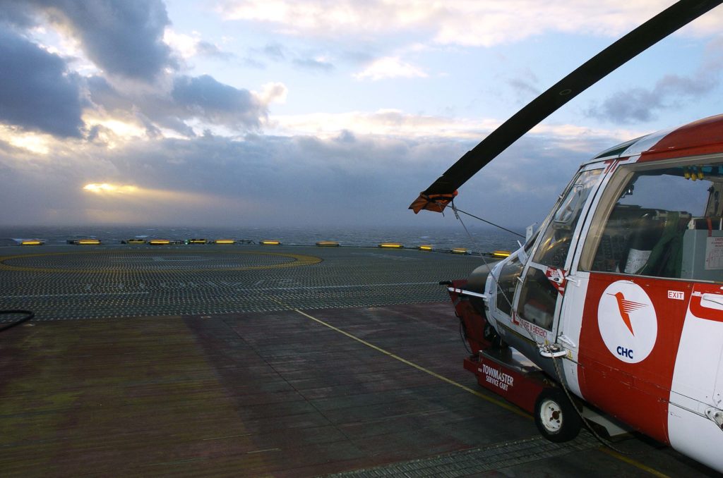
Its position and purpose of 2/4 H meant it had a lot of helicopter traffic. The helideck was therefore more extensively equipped than the equivalent structure on other installations in the Greater Ekofisk Area.
The most prominent extra facility was the hangar structure with associated goods reception. Other important details were broader stairs, access to lifts and a helicopter control tower. The helideck and associated equipment were certified for use through periodic inspections by the Norwegian Civil Aviation Authority and local pilots.
With a diameter of 25.2 metres, the helideck had an anti-skid coating and was covered by a net in synthetic fibre rope which prevented a helicopter from sliding or rolling over the deck.
The boundary of the landing area was marked with alternate blue and white lights. Floodlights were positioned close to the external stairs and on the hangar roof to illuminate the landing area.
 Ekofisk 2/4 H,
In September 1984, a new Safe Deck helideck was lifted into place on 2/4 H by the Balder crane ship. The Ekofisk Complex could thereby accept the big Chinook helicopters without the need for an exemption.
This deck was replaced in turn during 1991 because of cracking in the aluminium structure. Weighing 58 tonnes, the unit was lifted on board in sections and included a fire-extinguishing system. This network of pipes below deck could cover the surface in foam in the event of a fire.
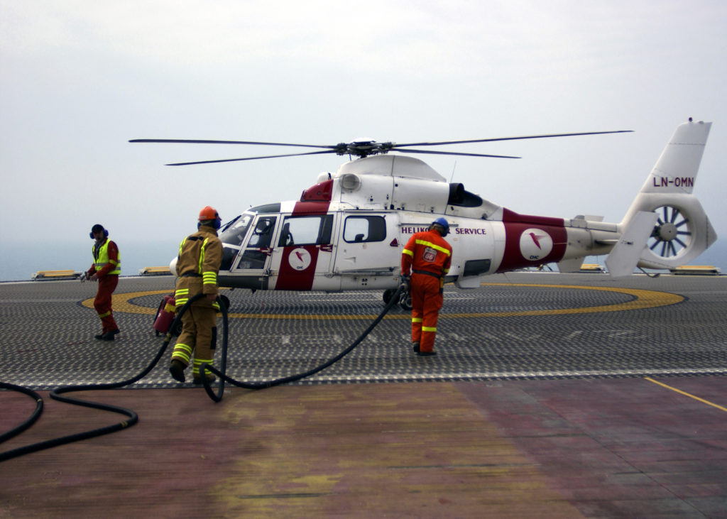
A filling station for helicopter fuel was positioned at the edge of the landing area.
In addition came a gutter and drain for removing water and possible spills of fuel or oil from the helideck and adjacent areas. This was designed with the same capacity as the foam/powder extinguishing system, which was operated from either side of the external stairs.
Hangar
Measuring 6.25 by 23.5 metres, this building had a rolling door and could accommodate a medium-sized helicopter with its rotors folded up. Space was then sufficient for maintenance and so forth.
The interior was warmed with heaters utilising hot water and placed at the eastern end. They were controlled by manual valves located on the southern wall.
A goods reception room was provided in the southern part of the hangar. Limited space meant that storage there was only temporary. A spiral staircase led down to the seventh storey and normal stairs to the control room. There was also access to the lift and its machinery.


Control tower
 Ekofisk 2/4 H,
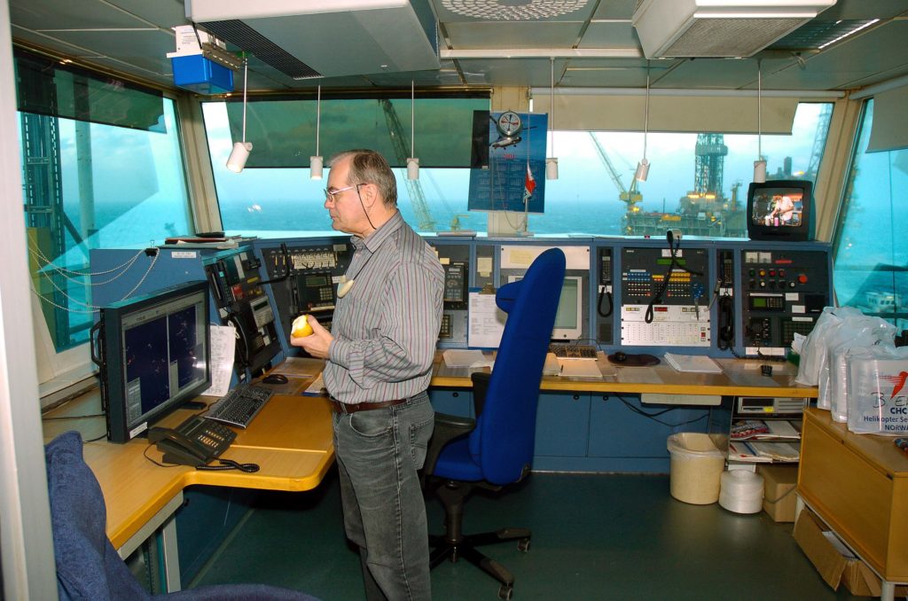
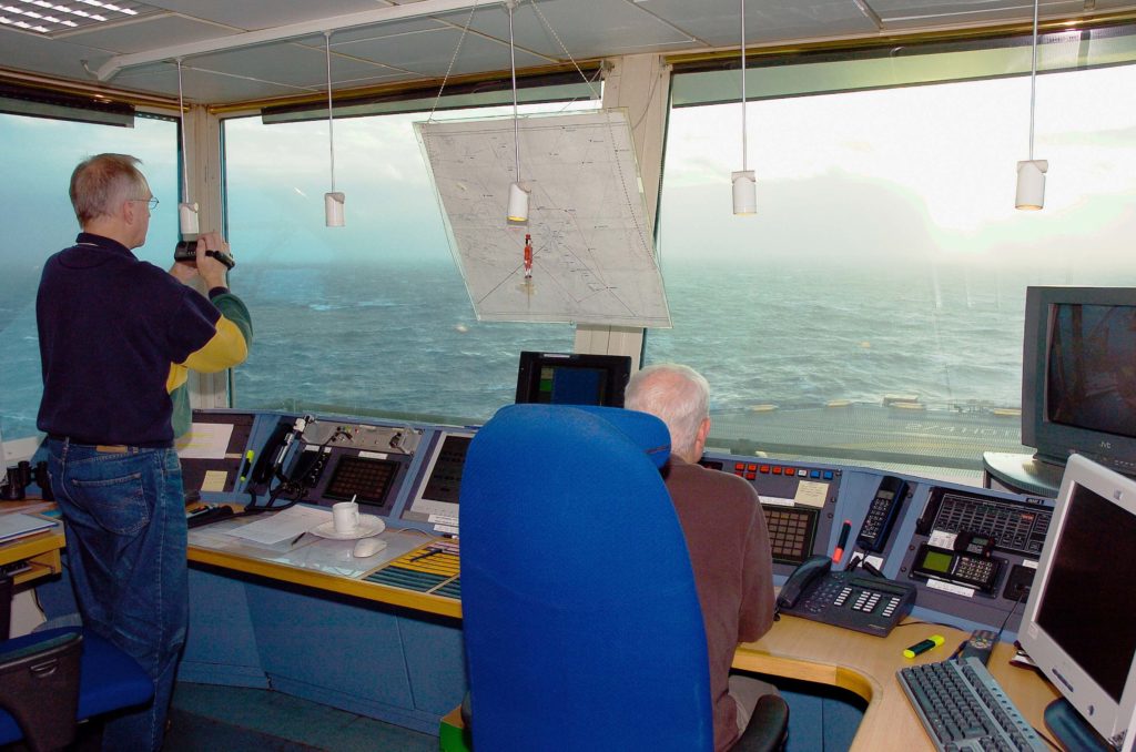
A control tower sat on top of the hangar to coordinate all helicopter traffic in the Greater Ekofisk Area and communicate with the Forus heliport in Stavanger. The controllers provided pilots with data on meteorological and landing conditions, and on transport of people and goods.
The 2/4 H tower had a direct phone link via satellite with the control tower at Stavanger Airport Sola to exchange information related to flights between Forus and Ekofisk and between Ekofisk and the pipeline platforms.
Shipping movements were initially controlled from Ekofisk 2/4 Q, but this was later shut down and the job transferred to the 2/4 H controllers.
Installed on 2/4 H in the winter of 1987-88, a considerably larger control tower provided space for additional functions. The weather and traffic services then acquired a common base.
Ekofisk 2/4 was provided with a wide range of communication systems. Many of these were replaced and modernised in 1996:
- telecommunications on the platform, with other Greater Ekofisk Area installations, with the pumping platforms on the pipelines to land, with the terminals in Teesside and Emden, and with the Phillips base at Tananger outside Stavanger
- connection from the platform to Norway’s public telephone network
- radio communication between the platforms and the Phillips base in Tananger
- platform-to-ship communication
- platform-to-helicopter communication
- platform to Norwegian coast stations in accordance with the 1974 international safety of life at sea (Solas) convention.
Communication systems on the platform included:
- telephone
- emergency telephone
- public address and alarm
- maritime MF/VHF radio
- aeronautical MF/VHF radio
- UHF paging.
 Ekofisk 2/4 H,
Electronic and mechanical aids were used to coordinate and ensure the safety of aircraft and ships. Helicopters were guided to the platform with electronic direction finders. Aircraft and ships were notified of platform positions with flashing and steady lights and foghorns.
Easy access to all areas of the platform was also ensured with the aid of stairs and lifts. A bridge to 2/4 C provided access to the centrally located installations in the Greater Ekofisk Area.
Alarms, shutdown and startup
Alarm, shutdown and startup systems on 2/4 H were largely designed to protect personnel. A system for visual and acoustic alarms ensured that people received adequate information everywhere on the platform at all times. Separate and clearly distinguishable signals gave notification of every type of crisis or its level of seriousness.
The shutdown and alarm system was intended to maintain essential services, notify people about hazardous or abnormal operating conditions and discontinue the affected functions.
Measures implemented automatically as a result of manual or automated warnings handled such aspects as:
- maintaining essential power supply
- identifying and warning about functional equipment faults
- shutting down equipment to protect against harm to personnel or equipment
- visual and/or acoustic alarms for alerting personnel
- full or partial platform shutdown.
All backup or emergency equipment could be operated manually. After a shutdown, functions had to be restarted in a safe manner and the startup system was accordingly aligned closely with the alarm and shutdown facilities.
Power supply
The most important power requirements on 2/4 H were met by three Solar Saturn GC1-SB turbine-driven generators. Nominal output for each generator set was 800kW of three-phase 480V 60Hz current.
These sets were designed for continuous fail-safe operation without supervision. Two operated simultaneously, with the third in reserve.
The electricity generated powered induction motors, lighting, current transformers, heating, communication and control functions.
A diesel-powered generator was provided to supply emergency power in the event that the main supply failed.
Fuel systems
 Ekofisk 2/4 H, yrker, helidekk, helikopter,
No production wells or hydrocarbon process systems were installed on 2/4 H. Its fuel requirements therefore had to be obtained from other sources. This covered diesel oil and gas consumed by equipment on board and aviation fuel for helicopters.
Diesel was delivered from 2/4 C through a common supply/return pipeline which ran over the connecting bridge. It could also be pumped directly from supply ships through loading hoses. The diesel system was segregated with check valves and a closed drain.
Gas also came from 2/4 C, again in a pipeline running over the bridge. It was used by the three turbine generators and two hot-water cylinders which were all designed for dual-fuel operation on either gas and diesel oil.
Helicopter fuel was supplied in large transportable tanks and transferred to a storage tank. During refuelling, it was either pumped from the storage tank or directly through water separator and monitor filters from the transportable containers.
Water and sewage
The fresh water system on 2/4 H met all the requirements on board. It was accordingly aligned closely with the water jetting and fire water systems. Three supply options were available:
- a watermaker (evaporator) on the platform
- water from a supply ship via hoses
- a two-way pipeline from 2/4 C which made it possible to share sources and supplies between the installations.
Jetting water system was installed to meet requirements for good order and cleanliness as well as for safety reasons. Jetting water was supplied throughout the platform, except in the accommodation areas, from the fresh-water distribution system.
The primary applications were cleaning up oil and chemical spills as well as general jetting of the decks. It could also be used for fire-fighting as and when required. Two jetting hoses used in addition to the helideck fire extinguishing system were supplied with seawater from other platforms in the Ekofisk Complex.
The fire water system ensured that large quantities of water were readily available for extinguishing fires. It was supplied from the fresh water tanks by two pumps – an electric one which maintained pressure in the fire main and a diesel-driven unit to provide additional pressure. Both pumps could be activated manually or automatically, but had to be switched off manually.
A separate powder/foam system was installed to provide additional protection for the helideck. As with the other utility/supply facilities, the fire-water system could receive assistance from the fire-extinguishing system in the Ekofisk Complex.
Open and closed drains comprised three systems on 2/4 H. The sanitary and rainwater facilities were both open, while the one for oil water was closed.
The waste water and sewage drain exited from the platform as an outlet pipe to the sea surface, while the system for rainwater and unpolluted liquid also used an outlet pipe which terminated slightly above sea level.
Oily water was drained to a sump tank and then conducted by pipeline to the system handling such polluted supplies on 2/4 C for treatment and discharge.