
Advanced reservoir monitoring in place

Known as life of field seismic (LoFS), this installation gives accurate measurements of reservoir changes over time in order to determine where more oil remains to be recovered. The network connected with fibreoptic cables which allowed the data acquired to be sent directly to the ConocoPhillips offices in Tananger for quality control and processing. It was the first system of this kind based on fibreoptics and the world’s largest in its day, and cost almost NOK 1 million to install. Operating the array to acquire and process seismic information added some NOK 200 million to the bill up to 2017.
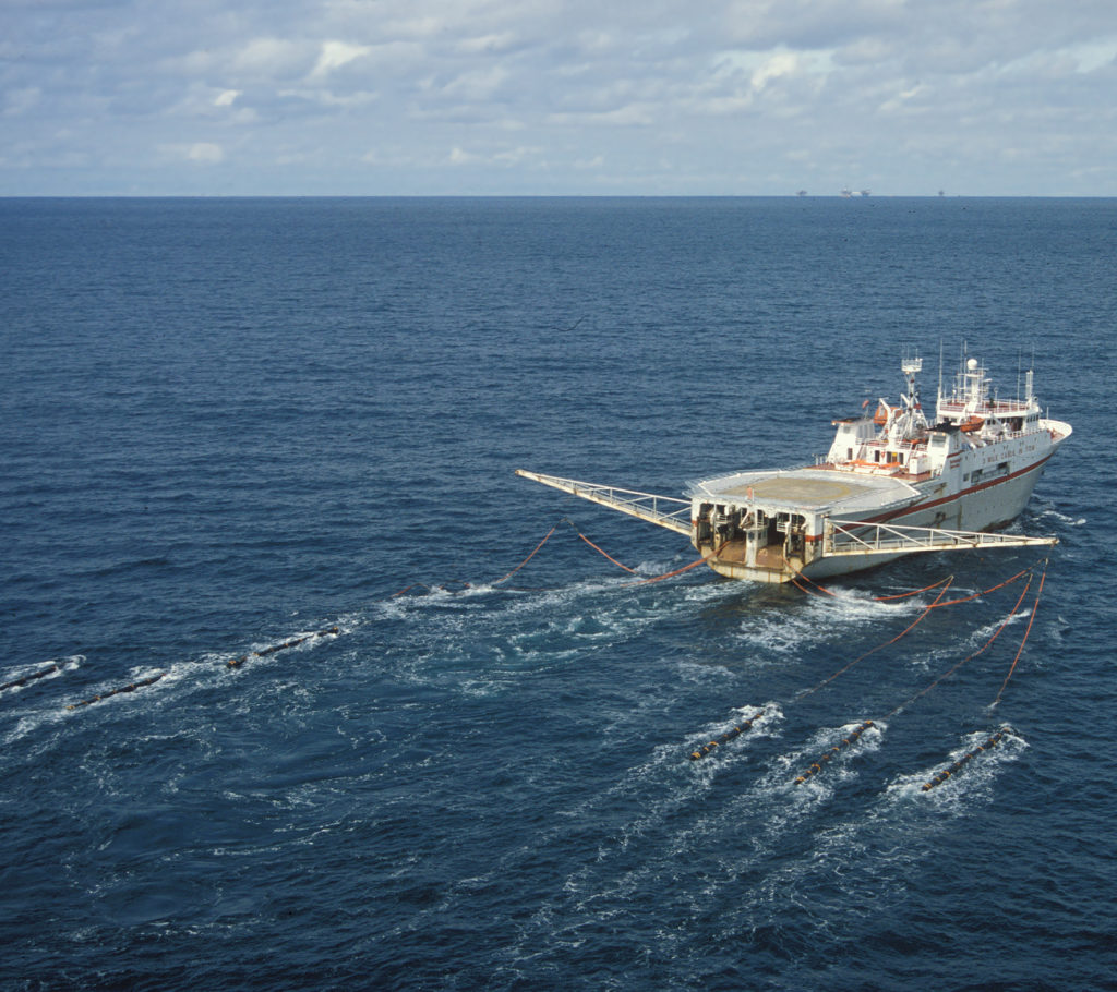
The LoFS system utilises a seismic source located in a supply ship, and is linked with an instrumentation module installed on the Ekofisk 2/4 M platform.[REMOVE]Fotnote: Passion & Knowledge, “Seismikk med permanente fiberoptiske kabler – et teknologisk nybrottsarbeid”, ConocoPhillips ONS magazine, June 2010.
Reservoir monitoring
The LoFS system allows the movement of oil and water through the reservoir to be monitored. Precision and detailing are better than with normal seismic surveying because the buried sensors can not only measure more parameters but also lie still – unlike those towed behind a ship. That makes it easier to record small changes in the reservoir over time. Detailed monitoring of such alterations are particularly important with waterflooding and other measures for improving the recovery factor.
With LoFS, the effect of water injection, for example, can be followed up over time. The effects of seabed subsidence can also be studied. This phenomenon is caused by compression of the chalk reservoir as oil and gas are extracted and pressure in the formation declines. However, waterflooding may not only maintain reservoir pressure but also dissolve chalk and thus increase subsidence. One effect of the latter is that production and injection wells become more quickly deformed and must be redrilled. Seismic surveying forms part of the process for determining where new wells are to be located in order to recover oil which has been left behind.[REMOVE]Fotnote: Ekofisk time-lapse seismic – a continuous process of improvement, first break volume 29, September 2011.
Gas cloud
 4D-seismikk på plass,
One reason why sensors were installed on the seabed is that parts of the Ekofisk and Valhall reservoirs are covered by a gas cloud in the overburden which complicates seismic imaging.[REMOVE]Fotnote: Larsen, André, Gas in overburden on Ekofisk, MSc thesis, University of Stavanger, 2007.
Traditional marine seismic surveying is conducted with cables and hydrophones which are towed behind a ship on the surface. That can make it difficult to obtain a clear image below gas clouds.
Four-component (4C) surveys can pick up shear (S) as well as pressure (P) waves. The former vibrate the ground in a shearing motion perpendicular to the direction of wave travel. Because they do not propagate through liquids, S waves cannot be registered by hydrophones at the sea surface. But seabed sensors can pick them up. Since these waves are also unaffected by the gas cloud, this provides an opportunity to secure more information on the underlying reservoir.
 historie, nytt boresenter og integrerte operasjoner, 2002,
Three-dimensional seismic refers to data acquisition which provides a 3D view at a given time, while four-dimensional surveys show changes over a period. This type of acquisition was achieved on Ekofisk by repeating 3D surveys first carried out on the field in 1989. Subsequent mapping occurred in 1999, 2003, 2006 and 2008.[REMOVE]Fotnote: Folstad, Per Gunnar, “Monitoring of the Ekofisk field with 4D seismic data from a permanently installed seafloor system”, Abstracts, IOR Norway, 2016. https://www.uis.no/getfile.php/13270844/IOR-senter/Abstracts%20IOR%20NORWAY%202016.pdf.
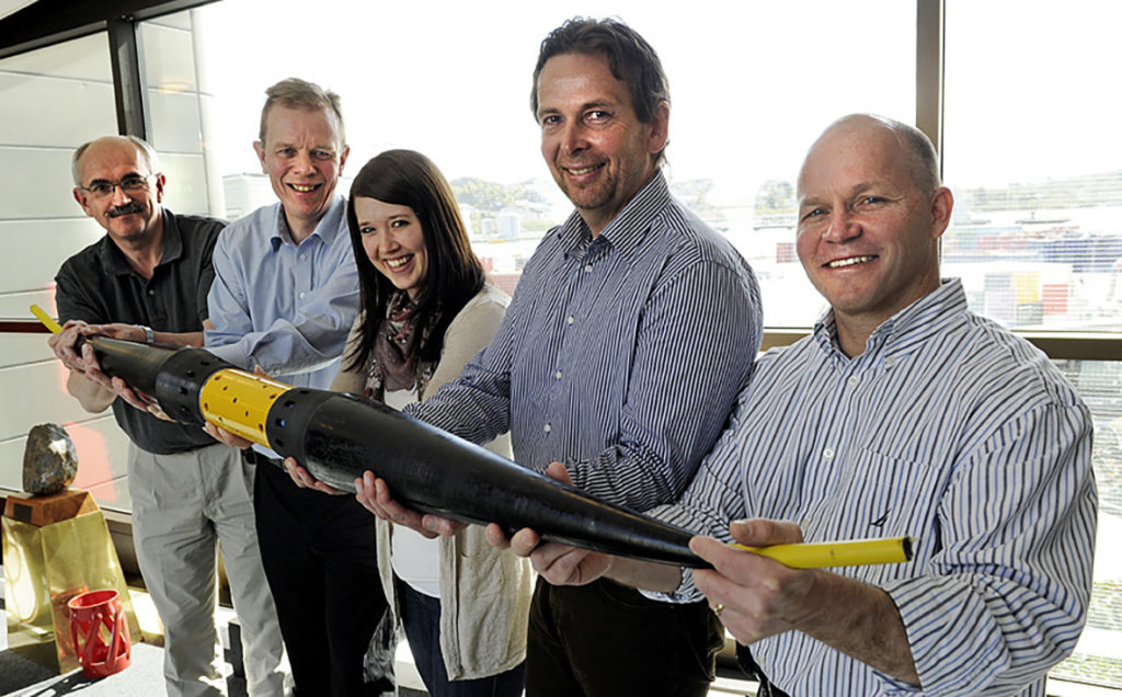
Experience from these exercises was used in testing the LoFS system before its large-scale implementation.[REMOVE]Fotnote: Pionér, no 1, “LoFS-prosjektet: Klart for permanente kabler på Ekofisk, 2009. Tests were done with cables based on both fibreoptic and electronic technology.[REMOVE]Fotnote: Nordsjøpionér, no 5, “Ny teknologi: Tester ut permanent seismikk”, 2008: 3.
Particle motions are registered by 4C seismic in three directions with the aid of geophones, and pressure changes in the water column using hydrophones. That adds up to four components. The LoFS system makes it possible to acquire data regularly and with high precision which show change over time. Two surveys per year are usually performed. In the intervening periods, moreover, the sensors can be used for passive acquisition – registering earthquakes, for example, and other movements on the seabed.
Fibreoptics essential
An essential requirement for a functioning LoFS system is fast data transmission and processing. Seismic surveys yield massive volumes of information, and these are best dealt with as soon as possible.
 4D-seismikk på plass
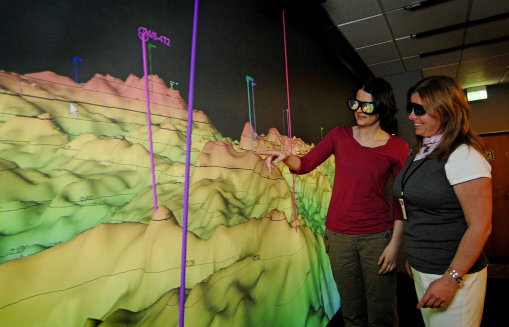
Mathematical and physical models are used to analyse the material with the aid of advanced computing tools and powerful computers and to build up 3D and 4D reservoir images. These can be accessed from a work station or reviewed in 3D. The big quantities of seismic data involved calls for rapid communication between the offshore installations and computing centres on land.
Operational from June 1999, the NorseaCom-1 fibreoptic cable between Kårstø in Norway and Lowestoft in the UK passes via a number of British and Norwegian oil fields. These include Ekofisk, Valhall and Ula, and all telephone and data communication between Tananger and Ekofisk was transferred from satellite transmission to the new system on 1 August 1999.[REMOVE]Fotnote: EkofiskNytt, no 15, “Fiberkabel – nå og for framtiden”, 1999.
This was the first fibreoptic link between Scandinavian and Britain, and the first commercial telecommunication cable to utilise oil platforms for a lengthy sea crossing.[REMOVE]Fotnote: Teknisk Ukeblad, “Nye driftsformer”, 17 August 2000.
NorseaCom-1 later became part of the Tampnet communication system, and was tied into a wider network for communicating and transferring data across the North Sea.[REMOVE]Fotnote: Tampnet Offshore FOC Network, 16 May 2019, accessed at http://www.fiberatlantic.com/system/rk94K.
 2/4 – M plattform, forsidebilde, engelsk, historie, 2005, oppstart av ekofisk vekst med 2/4 m,
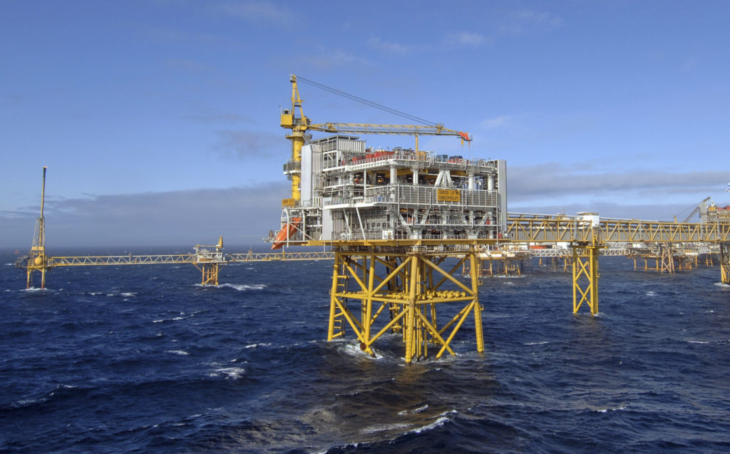
The new 2/4 M platform was installed on Ekofisk in the summer seasons of 2004-05. It carries receiving equipment related to LoFS for onward data transmission by fibreoptic cable to the Tananger processing centre.
Within a short space of time, experts on land could thereby analyse and interpret data acquired from the seismic surveys.
Ekofisk 2/4 VACoordinating maritime traffic from land