
Ekofisk 2/4 B

Collision damage to one of the jacket legs delayed the installation process. It was not until May 1973 that the jacket had been fully piled and was ready to accept the topside modules.
However, progress was then rapid and all the modules were lifted on board during June-July. Three months of hook-up and commissioning followed before the first of the two derricks – rig 41 – spudded the first production well. The second derrick required more work, and first became operational in December.
A trial project for water injection in the Cretaceous formation began via well 2/4 B-16 in April 1981. The aim was to assess whether waterflooding across the whole field could improve oil recovery. Positive results from the trial led to a decision to adopt this approach.
In April 1985, it was also decided to extend waterflooding to the Danian structure using the same equipment as with the Cretaceous formation.
Ekofisk 2/4 K was installed alongside 2/4 B in 1986 to inject water in the northern part of the reservoir, and Ekofisk 2/4 W was installed on a bridge support south of Ekofisk 2/4 FTP for injecting water in the southern area.
Ekofisk 2/4 B and 2/4 K were integrated operationally in January 1995 as Ekofisk 2/4 K-B. Both platforms were thereafter run from the 2/4 K control room.
One of the 2/4 B derricks was removed first, followed by the second in 1997. The 68-bed accommodation module was taken away after 2/4 K had been installed. A bridge now connects the two platforms.
Three oil and gas pipelines of 10, 18 and 22 inches respectively connected 2/4 B to 2/4 FTP. An eight-inch Coflexip umbilical was laid to 2/4 C in 1985. The platform weighs about 12 000 tonnes.
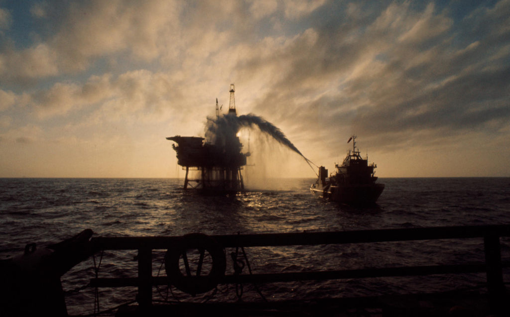 Bravo-utblåsningen, historie, forsidebilde,
An uncontrolled blowout of oil and gas occurred from 2/4 B in April 1977. Well B-14 needed a workover, which meant pulling out the 3 000 metres of production tubing. The blowout preventer failed during this operation, and it took a week to bring the well back under control. See the article on the Bravo blowout in the history section.
The process comprises two identical production separators (each 12.2 by three metres) in parallel and a test separator (6.1 by 2.1 metres). This equipment was designed with a view to supplying crude oil from the reservoir to 2/4 FTP.
Of the 24 well slots on the platform, 22 were drilled and completed for this purpose and two held in reserve. These wells delivered a mix of crude oil and natural gas through the production manifolds or a test manifold. Output was piped directly to 2/4 FTP.
Wellheads
With each of the 22 production wells, casing and production tubing was set from the wellhead and through the reservoir. Seated on the casing, the wellhead provided a system for controlling pressure in the tubing.
Driven by pressure either from the reservoir or provided by injection support, the crude oil and gas flowed up through the tubing to the wellhead.
On top of the latter was a set of production and work valves known as an Xmas tree, which controlled the wellstream as it flowed to the manifolds and was also used to shut in production.
Each wellhead was equipped with the following valves.
Downhole safety valve
This hydraulically operated ball valve stood far down in the production or injection well. It closed automatically (fail-safe) if the hydraulic pressure was lost.
A line for hydraulic fluid accordingly ran from the wellhead to provide the pressure required to open the safety valve. When the latter closed, the well was shut in and all equipment on the platform was isolated from the pressure in the well.
Faulty installation of such a ball valve was one of the reasons for the Bravo blowout in 1977.
Manual and automatic master valves
These sat in the vertical section of the Xmas tree. The automatic (upper) master valve was kept open by hydraulic pressure. Supported by the manual (lower) master valve, it formed the second barrier against pressure in the well. During the Bravo blowout, this valve was also incorrectly installed and was a direct reason why the well could not be shut.


Manual and automatic wing valves
Flow wing valves for production were positioned in the four-inch horizontal section of the tree and connected to the choke. These are the valves normally used to shut down a well.
Manual chokes
These were designed to cope with a substantial pressure drop. They were used to regulate oil flow and pressure to the production and test manifolds.
Kill wing valve
This allowed diesel oil to be injected into the wellhead in order to increase pressure in the production tubing above the downhole safety valve. It could also be used to inject various chemicals during maintenance of the wellhead and the main pipelines.
A pressure gauge was installed on the Xmas tree to measure well pressure.
Manifolds
Three manifolds were used on 2/4 B to integrate flows from the various wells for delivery to the main pipelines. Two had larger diameters in order to accommodate the main production stream, while the third was narrower since it received the flow from a single well for testing.
During normal operation, output from all the wells was conducted to the two production manifolds and on to the two main seabed pipelines connected to 2/4 FTP. The flow from a well being tested was diverted to the test manifold and through the platform’s test separator.
Gas lift
This system was designed to import gas by pipeline from 2/4 FTP. Its pressure was then raised for continuous injection into the wells in order to “lift” the oil and boost the production flow.
Two different operational settings were built into the system – initial compression and gas lift. The first was used to initiate lift and required higher pressure than the ongoing operation. Once initial compression was completed in a well, the latter switched to continuous gas lift. This required less pressure but more gas. The settings could be used simultaneously.
The system comprised two gas scrubbers to remove possible residual liquid, a four-cylinder compressor for raising gas pressure, a motor fuelled by natural gas to power the compressor, and separate manifolds for initial compression and gas lift.
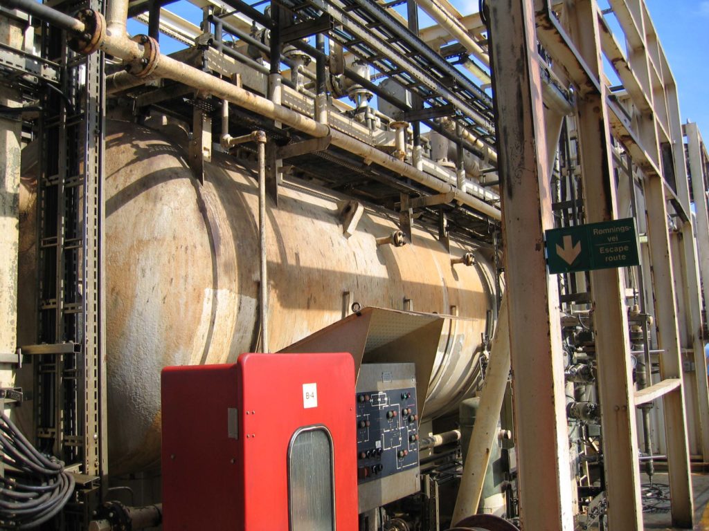 Ekofisk 2/4 B,
Test separator
Production from each well had to be tested to monitor reservoir/well conditions and to check separation/treatment. A good monitoring programme was also needed for waterflooding, so a permanent test separator was installed. Its design was based on a vertical cyclone principle.
Utilities
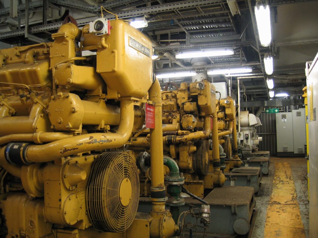 Dieselgenerator, 2/4 B, engelsk,
Utilities on 2/4 B included systems for telemetry and communication, safety, hydraulics, electricity generation, fuel and lube oil, instrument and work air, and chemical injection.
Other facilities covered pig launching, seawater, jetting and fire water, untreated seawater and drinking water, gas flaring and venting, oil recycling, steam generation, and cranes and lifting.